
The heater on my 1956 3 litre would not turn off; the valve was checked and found to let water by even when off and moving the controls had no effect on the air flow which was always hot. I decided to remove the heater box and investigate. Not many tools are required, a screwdriver or socket for the hose clips, 2BA and 4BA spanners and a 2BA socket with a long extension. It is fairly important to use 2BA as 8mm or 5/16"AF does not always fit, especially if they are new spanners or sockets.
Removal of the heater is fairly simple. First, drain down the coolant enough to allow removal without too much loss of fluid.
Remove the two pipes from the unit and the large air inlet duct tube and undo but do not remove the studs on the cables for the flap control. A 4BA tool is needed for the inner cable fixing and 2BA on the outer fixing.
Remove the bolts or screws attaching the heater box to the bulkhead. They should require a 2BA socket on a long extension but they could be slotted screws.
The box can then be lifted off but will probably be stuck to the bitumen fabric sound-deadening insulation. It will need to be prised up at the front enough to break the seal to the bitumen and then the top back to the bulkhead can be tilted and pulled forward. There is an outlet at the bottom to the interior air deflector and two pipes at the back for demist. The unit needs the tilt to enable it to slide forward to get over the bottom air deflector. The demist pipe will not allow the back to lift. When trying to pull the box forward the pipe at the back will probably be stuck to the rubber demist bends that are fixed to the bulkhead. It may be necessary to free off these from inside the car and the carpet will need to be moved out of the way. Then the rubber demist bends can be twisted to break the seal. The heater box can then be pulled forward enough to disengage the demist pipes and control cables and lifted out of the engine bay.
To strip down the unit, first remove the water valve. There are two setscrews holding it on the unit which require a 2BA spanner. They can only be undone a bit at a time and the valve gently eased forward a bit at a time. As the valve is aluminium on a tinned copper spigot of the heater matrix there could be corrosion holding it tight. Care and patience are needed. Removal will reveal a plate with a rubber olive bonded to it. This is a seal and it is compressed when the valve is fixed to the unit. The clips that hold the box together can be prised off with care so as not to damage the case.
The front panel can be eased forward; the top spigot is a loose fit but the lower one has the valve fixing attached to the case and is a fairly tight fit over the spigot. This can be gently eased off the spigot. The front plate needs to be lifted off both spigots equally. The back plate will lift off easier but the grommets may be stuck to the aluminium demist pipes. Inserting a small screwdriver to break the seal may help.
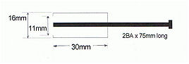
To remove the final part of the case, a puller is needed to remove the flap-operating levers; a miniature two claw puller will do. I made up one using 20mm by 2mm steel as per sketch. The levers will pull off quite easily and with these removed the last part of the case can be lifted off and the heater matrix lifted out.
The heater matrix can be separated from the base by prising off the clips. Care must be taken to avoid damage to it. It can now be checked over and tested for any leaks. It was at this point that I found out why my heater did not respond to controls.
The flaps have felt pads stuck to them or should have. The demist flaps had come off and one of the flaps to the interior vent was stuck in the open position. This one is operated by the demist flap. When defrost is required, an arm of the demist flap has a curve in it that pushes against a pin on the interior vent flap that should close it against a spring, but with age and corrosion the cam could not slide up the pin. I made a slight modification; I cleaned up the pin and fitted a roller on the interior vent flap that should close it against a spring clip (click here for photo 9). The last flap controls the air to the interior either through the matrix or around it (hot or cold air) and the felts come off making the air go through the matrix permanently. The felts were all glued back on using impact adhesive and the operation of the felts are now satisfactory.
The matrix was then fitted back on and it is bedded at each corner with putty-like mastic (click here for photo 11). I had some bedding mastic to hand, it is like Blue Tack. The old Dum-Dum sealing mastic is still available and this is what was probably used. To fit the clips back takes some effort. I bent some 3mm rod about 300mm long to form a loop, then a hook to 90 degrees about 15mm long. This enabled me to engage it in the clip and pull it over the case. With two people, it would be easier as it really needs three hands to do it or the base could be clamped to a bench. It is only the second clip which needs this.
Next, the centre case can be fitted back on. Then the actuator levers need to be tapped on using a nylon or hide mallet. It does not take much force to get them back on. Check for correct operation of the flaps. The front panel is next to be fitted and must go on square. Fit over the top spigot first but not too far and then slide over the bottom spigot. I used silicone grease on the spigot; it helps sliding and hopefully will prevent corrosion. The rear case is than fitted using the bent rod to help with the clips. The heater valve is next to be fitted. I put some silicone sealant in the depression on the flange fitted to the box and then slid on the plate with the rubber olive and put a small amount of silicone sealant on the valve depression and then bolted it back on. I left this overnight to allow the sealant to set.
The demister pipes were a bit sharp on the edges so to make sliding them back in easier I chamfered them with a file.
On the bulkhead the interior air deflection plate has a gasket which will almost certainly have degraded. A new one can be made out of closed cell foam rubber about 10mm thick. This is readily available from rubber suppliers (click here for photo 19).
Fitting the unit back into the car is easy but getting the cables back into position is a bit awkward. The unit needs to go in at a slight angle tilting back at the top. Get the demist pipes about to enter the hose in the bulkhead and try to get the cable into position before sliding it home. A good push on each side at the bottom will help get the unit back home and then you need to line up the fixing holes. A scriber or small screwdriver will help location. Get all screws started and then tighten them up.
Finally, cables need fixing. The outer ones will only fit in one place as they have a collar but the inner cables will need trial and error to get them right. The demist cable was not too bad. However, the air control flap also controls the water valve and this can take a bit of time to get it positioned. I think that there should be a spring from the small bracket on the water valve to the operating arm. This would make for a better operation.
(Click on photos to enlarge)


Robin Allum